¶ Getting It Inside
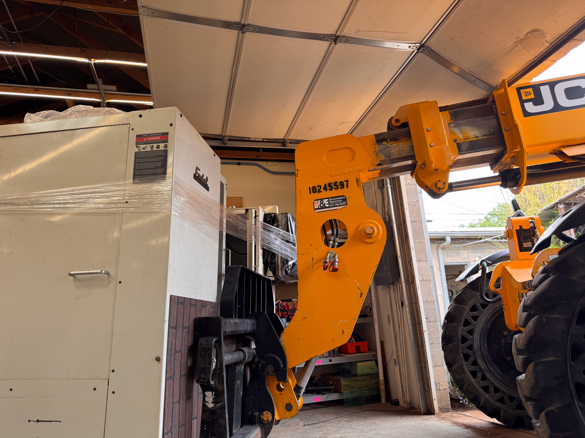
At nearly 8,000 pounds, moving the VMC was an adventure in itself. We rented a telehandler capable of transporting the machine and, with the skilled support of Stark Raven Fabrication, maneuvered it into the shop and set it in its permanent home. We only had one minor tip-over.
¶ Z-Axis Assembly
To clear our roll-up door, the Z-axis had to be disassembled before the move. Once inside, we carefully reassembled the head assembly and aligned the axis to ensure smooth and accurate motion.
Will Putnam, the donor, helped us get the z-axis properly put together and aligned.
¶ Power & Controls
The Fadal required a dedicated electrical setup and careful work on its control systems. Once a three-phase 220v circuit was added, we were able to power on the machine. Unfortunately, this also meant we discovered some things that needed to be fixed.
¶ The video monitor
We learned from the previouys owner that the screen might need a new power supply, so we checked to see if that was indeed the case. After some short troubleshooting, we found that the power supply worked as expected. But the screen did not function.
The problem turned out to be the screen itself. It was a 30-year-old screen with some old and unnecessary components. We replaced the screen with a modern HDMI flat screen.
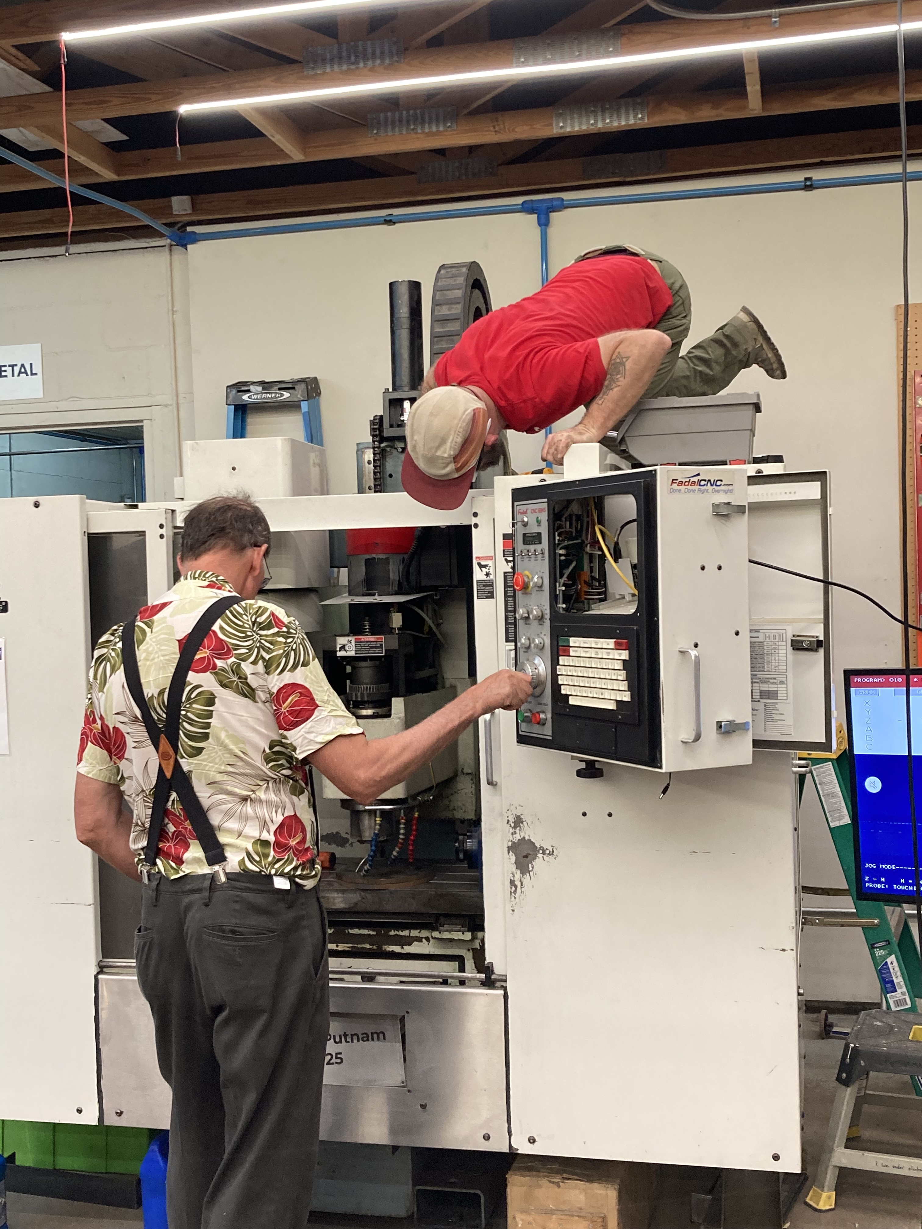 Charles, a member, helped us get the control system working. Note the missing screen in the pendand, but we had it hooked up to a television on a stand.
¶ The Controls
To our surprise, every button on the pendant worked! Toggling into JOG mode gave us complete control of the machine.
¶ Repairing the Y-Axis Servo
We’ve been having ongoing issues with the Y-axis on the Fadal for quite some time. After even minimal use, the motor would heat up significantly and pull far more current than it should. A few weeks ago, I decided it was time to seriously track down the cause. I powered up the machine and spent some time observing it, the problem quickly got worse.
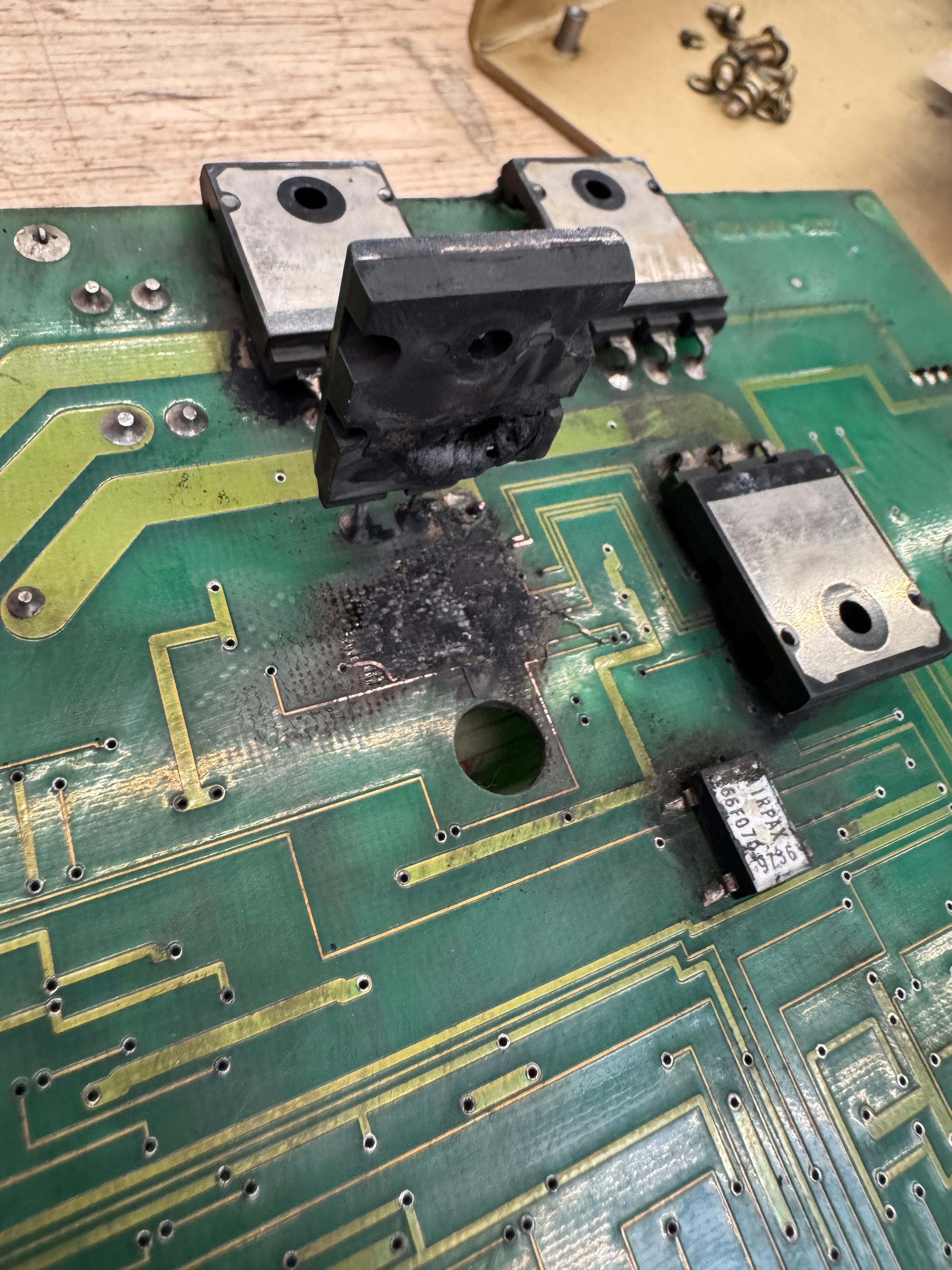
Then came the catastrophe. Sparks shot out of the enclosure! Thankfully, I was able to kill the main power almost immediately, hopefully preventing even more damage, but the machine was dead.
After tearing into it, I discovered that the Y-axis had essentially destroyed itself. The motor had drawn so much current that it blew a large power transistor in the servo amplifier. That raised an obvious question: why didn’t the fuse blow first?
The answer turned out to be… human error. Someone had installed a 50A fuse where a 20A fuse should have been. Most likely, the original fuse kept blowing because the motor was already failing, and rather than addressing the root cause, a larger fuse was installed to “solve” the problem.
My first assumption was mechanical binding in the Y-axis. On machines like this, alignment is critical. The motor must be perfectly parallel to the ways that the table rides on. I pulled the motor and tested the table movement by hand. Everything slid smoothly. No binding.
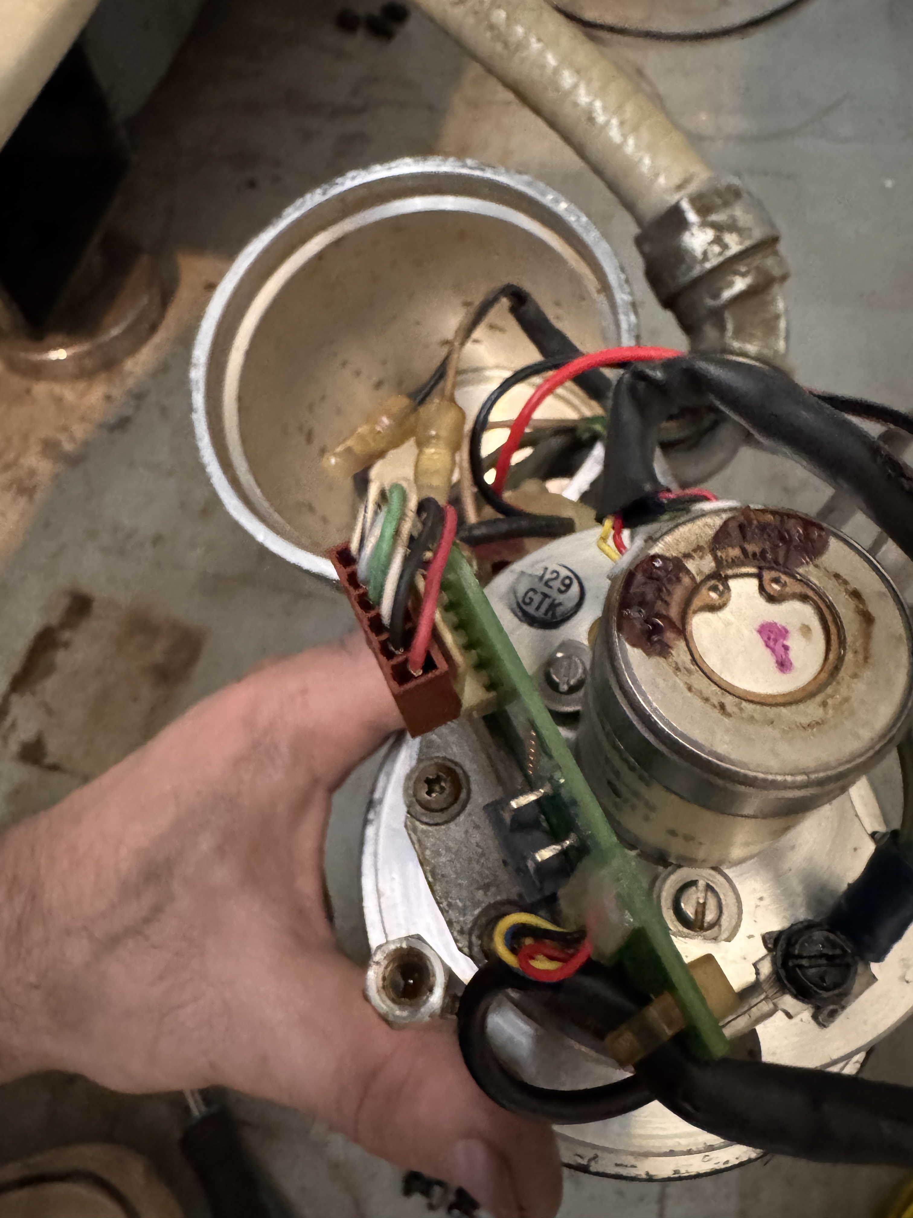
So I turned my attention to the motor itself.
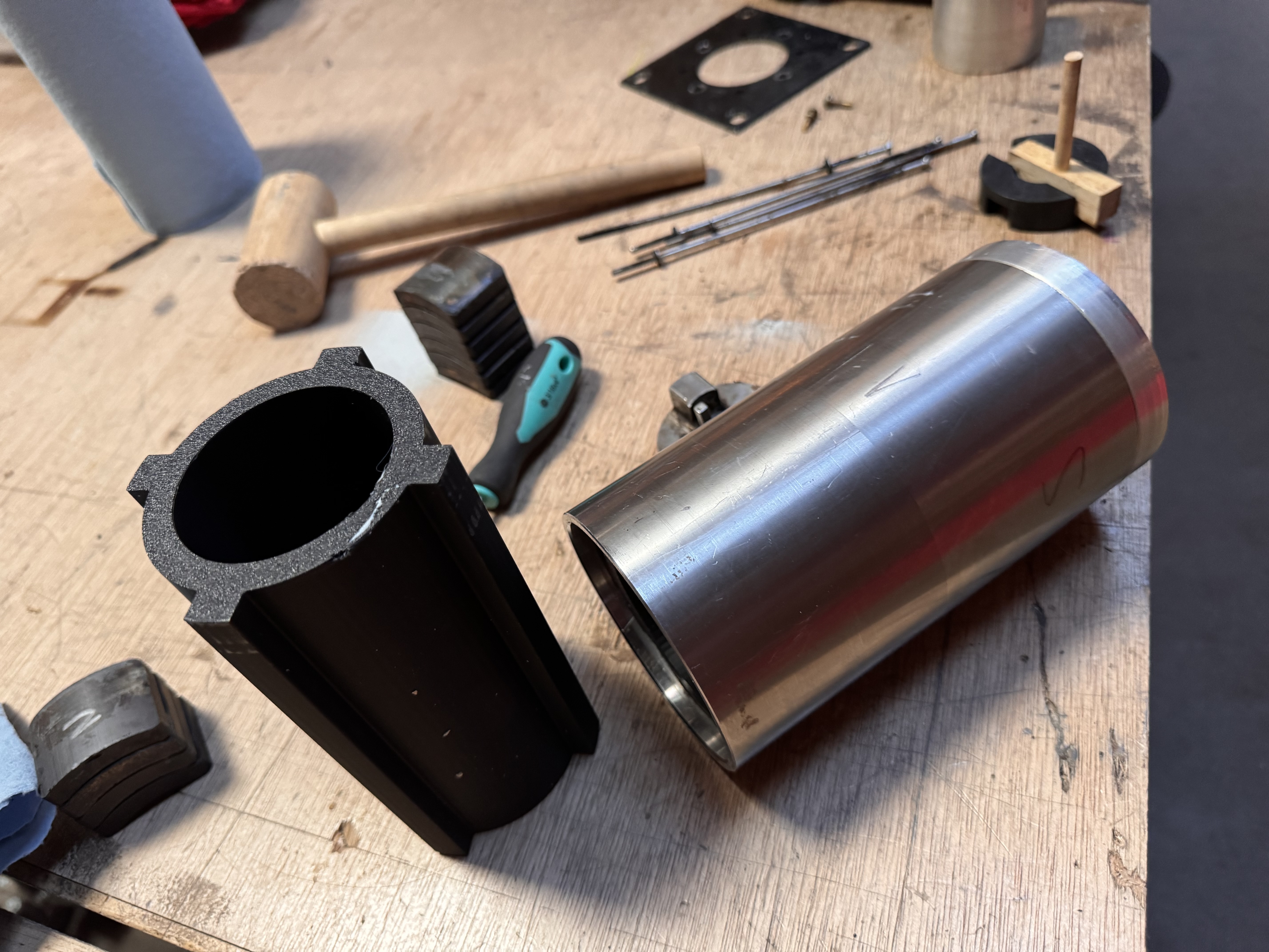
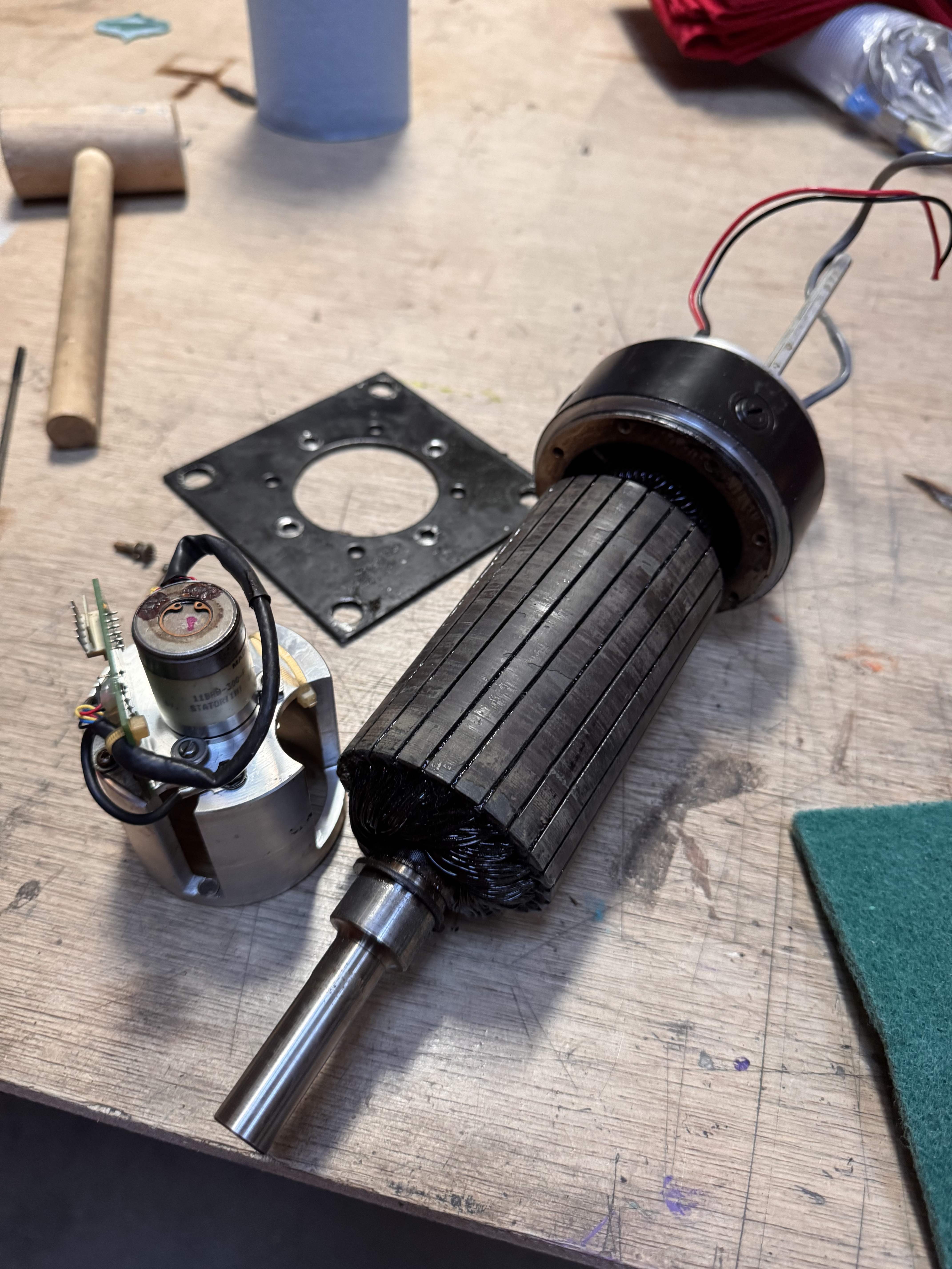
When I rotated it by hand, I could feel and hear grinding which is usually a clear sign of a bad bearing. But when I opened the motor, the real problem revealed itself: the internal stator magnets had come unglued and attached themselves to the coils. The motor was effectively toast.
What likely happened is this: one magnet came loose a long time ago (possibly due to age or heat) causing the motor to draw excessive current and blow the original fuse. Instead of fixing the motor, someone upsized the fuse. The motor continued to run, but it generated even more heat, causing additional magnets to come unglued. By the time I started using the machine more regularly, the damage had progressed to the point where the motor pulled enough current to destroy the amplifier.
So… time for a new motor.
Except a used replacement costs around $2,000.
So, time to repair the original motor.
Because the magnets had to be positioned exactly right, this wasn’t as simple as gluing them back in. With help from @Hubert van Hecke and a few others I worked out the correct magnet locations and designed a 3D-printed fixture to align them precisely. Working slowly, row by row, I reinstalled every magnet in the housing. Once that was done, I reassembled the motor using a mix of old-school techniques, controlled heat to expand the housing and a hydraulic press to bring it all together.
Then came one of the most frustrating moments of the entire process.
When I went to reinstall the long through-bolts… they snapped. I had used the wrong holes. That meant everything had to come apart again so I could extract the broken screws and start over.
But, finally, it all came together.
The motor is now fully assembled and bench-tested, and it works beautifully. At 24V it pulls about 3 amps, exactly what I expected. As the brushes wear in, that current draw should drop even further with use.
Tomorrow, the motor goes back onto the Fadal—and with any luck, we’ll be back up and running.